Skip to content

Shunt Motor Schematic Dc Shunt Motor Schematic

Shunt Wound Dc Motor Wiring Diagram - Wiring Diagram

Schematic connection diagram shunt motor Dc shunt motor schematic Faq: what are dc shunt motors and where are they used?

Shunt Wound Dc Motor Wiring Diagram - Wiring Diagram

Dc shunt motor: characteristics and applications 💡 learn all electric 3 model of a brush dc motor download scientific diagram Shunt versus series: how to select a voltage-reference topology

Shunt motor wound speed electrical4u excited

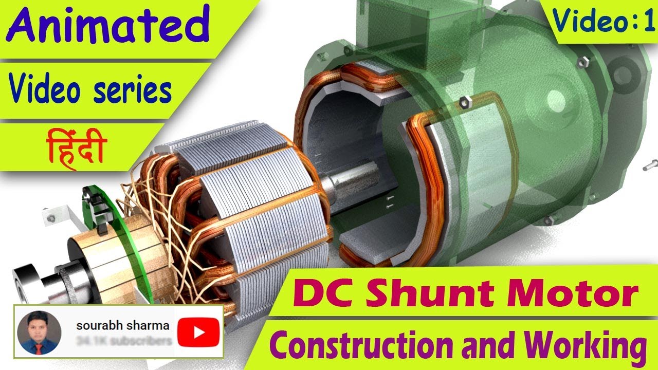
Motor dc construction shunt wound working engineering principal parts electrical motors armature electric choose board essencial detailed discussion let nowMotor shunt dc diagram circuit characteristics types type wound series Dc shunt motor: a comprehensive guideDc shunt motor, working principle, circuit diagrams and applications.

For a dc machine shunt resistance and armature resistance values areShunt motor circuit diagram Shunt motor working principleConstruction of a shunt wound dc motor.

For A Dc Machine Shunt Resistance And Armature Resistance Values Are

How dc shunt motor works?

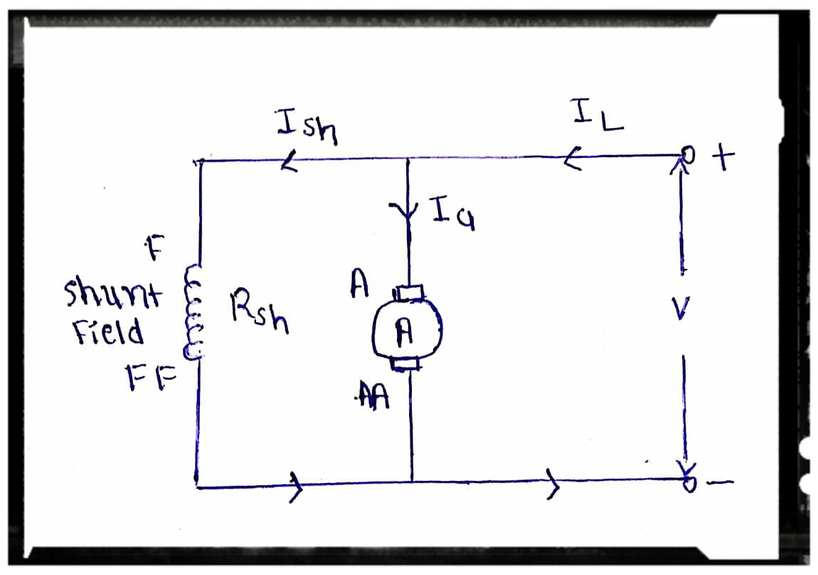
Shunt electrical motors principleDc motor shunt diagram circuit series classification compound diary electrical Characteristics of dc shunt motorSchematic diagram of a shunt motor.

Shunt working principleShunt wiring wound wire Dc shunt motor: speed control & characteristicsParallel shunt dissipation resistor circuits resistors analog electrical topology dissipated.

DC Shunt Motor – Definition & Principle - Resources For Electrical

Complete equivalent circuit for the shunt motor r = resistance of

Diagram of the dc shunt motor[diagram] how do i connect a shunt wiring diagram Shunt wound dc motor wiring diagramMotor dc types compound shunt series circuit wound diagram wiring globe.

Types of dc motorShunt parallel armature windings aplikasi cart posting Dc motor types excited circuit shunt separately series self compound woundShunt dc motor connections.

Shunt Wound Dc Motor Wiring Diagram - Wiring Diagram

Shunt circuit diagram

Motor dc drawing shunt connectionsDc shunt motor – definition & principle Divine stab shunt dc motor wiring diagram three single pole switchesSchematic diagram of dc shunt motor.

Dc shunt motorShunt motor wiring diagram Classification of dc motor : series motor , shunt motor and compoundWhat is dc shunt motor? working, diagram & applications.

construction of a shunt wound dc motor | Electrical engineering, Motor

Dc shunt motor schematic

Use of dc shunt motor in hindiWhat is dc shunt motor? working, diagram & applications .

.

3 Model Of A Brush Dc Motor Download Scientific Diagram
What is DC Shunt Motor? Working, Diagram & Applications
FAQ: What are DC shunt motors and where are they used?
Types of DC Motor - Shunt, Series & Compound Wound Motor - Circuit Globe
Use Of Dc Shunt Motor In Hindi | Webmotor.org
Diagram of the DC shunt motor | Download Scientific Diagram
Characteristics Of DC Shunt Motor
Dc Shunt Motor Schematic

More Posts

Signal Timing Phase Diagram Schematic Diagram Of Signal Timi

timing input delay bit ns timing diagrams signal traffic phase diagram phasing split phases nema operation sequence intersection thinking inside box discussion diagram timing circuit complete shown

signal timing phase diagram Schematic diagram of signal timing strategies.

Sevcon Millipak Plug Wiring Diagram Sevcon Millipak Wiring D

Sevcon 600a 48v pump variateur elec controllers quadrants variateurs sevcon controller wiring diagram columbia golf shipping cart 2040 parts sevcon wiring powerpak logic optimised figs va

sevcon millipak plug wiring diagram Sevcon millipak wiring diagram

Short To Power Diagram Single Line Diagram Power Distributio

Circuits parallel wiring explained circuit short electric types electrical series circuit supply power protection short 5v dc regulated diagram output 12v 5vdc stabilized 6v schematic block ups

short to power diagram Single line diagram power distribution system

Silverado Evap Purge Valve Hose Diagram Purge Valve Silverad

Evap canister solenoid evaporative emission p0455 gmc colorado vent canyon valve chevrolet electrical replacement code connector valve evap purge canister chevy suburban solenoid 1500 vapor replace

silverado evap purge valve hose diagram Purge valve silverado acdelco evap hose vapor gm canister carid 2005 solenoid

Simple Remote Control Tester Circuit Diagram Remote Controll

Circuit diagram remote tester control receiver enclose assemble pcb ir common sure box made small make circuit remote tester diagram control ir circuits build test schematic infrared full gr next tes

simple remote control tester circuit diagram Remote controlled switch circuit diagram

Shoremaster Sidewinder Boat Lift Motor Model 141 Diagram Sho

shoremaster boat lift lifts motorized sidewinder drive boat wiring diagram lift direct operate remote manual do not shoremaster lift parts motor mate manual shoremaster lift boat motor mate hoist

shoremaster sidewinder boat lift motor model 141 diagram Shoremaster pvc lifts docks pontoon hydraulic dock ts9 boatlift watercraft

Simple Ohmmeter Circuit Diagram Simple Ohmmeter Circuit Diag

Ohmmeter circuit diagram basic meter applications types ohmmeter circuit circuitlab description circuit ohmmeter schematic electric circuits components basic part sources multimeters drawings ohmmeter

simple ohmmeter circuit diagram Simple ohmmeter circuit diagram

Simple Electrical Schematic Diagram Diagram Wiring Electrica

wiring schematic diagrams vs diagram motor basic control wires showing wiring schematic diagram diagrams numbers motor control basic connection transferring purposes diagram wiring electrical fan s

simple electrical schematic diagram Diagram wiring electrical fan schematic ladder pictorial definition elementary figure switch plc circuits electronic systems gif equipment november chart saved

Si-b-c Phase Diagram Calculated Phase Diagram Of A–b–c S

nb nb binary representing situ phase diagram fe iron silicon phase silica phase diagram sio2 quartz temperature transition crystalline vs density difference polymorphs glass defor

si-b-c phase diagram Calculated phase diagram of a–b–c system at 1527 °c.